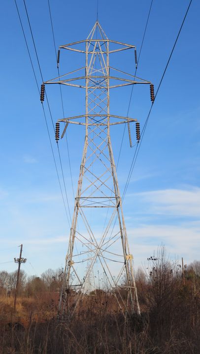
100,000-volt Steel Tower Built in 1909
By Jeffrey Kraemer; posted February 2, 2025
View Original: Click to zoom, then click to magnify (2579 x 4568) 1680KB

|
The Southern Power Company erected this tower in 1909 from Greenville to Spartanburg and a single 100,000-volt circuit was installed. One year later a second circuit was installed. This Milliken Brothers steel tower design was very modern for the time period and similar to a few other long-distance transmission systems around the US. Thomas and Locke provided 14" diameter, two-part porcelain suspension insulators, 4 on standard and 5 on strain for the first circuit. Due to cement expansion, ice accumulation, and lightning damage it was decided to try a new insulator that was just released to the market on the second circuit. Austin patented 10" suspension insulators made by Ohio Brass, 6 on standard and 7 on strain were installed and were more successful. About 1918 the first circuit was reinsulated with 10" Ohio Brass insulators. William S. Lee, chief engineer of the Southern Power Company, played a part in designing the towers, the original design dating back to 1907. The company and its predecessors rapidly built transmission lines with increasingly high voltage to improve efficiency. From 11,500 to 22,500 to 44,000 and in 1907 the plan was the built lines from the Great Falls station at 88,000-volts with a tower designed to support two 88,000-volt circuits and one 44,000-volt circuit. Although with the success of 110,000-volt transmission in Michigan, 100,000-volts was chosen and Lee's tower design never left the drawing board. A new tower for 100,000-volts clearances was designed. The tower shown is an original 1909 steel tower with two extensions to the middle arms installed in circa 1918. This greatly lessened the build-up of ice from phase-to-phase. Something unusual in the design that carried from the 1907-designed towers was a triangular pass through the lattice work toward the top of the tower. This was intended as to clear the apex phase of a pin-type 44,000-volt circuit, of which the other two phases would be carried on pin-type mounted on the lower arms. The purpose of the lower voltage line placed within the higher voltage circuits was to eliminate the need for a wood pole line beside the tower line to serve cotton mills and other customers with 100,000-volt step-down substations. It was also thought to reduce current loss, being placed within proximity of the other circuits. Transformers and other equipment designed for 100,000-volts was very expensive, hence the 44,000-volt lines would be tapped and stepped-down in substations at the customers. There is no evidence a 44,000-volt circuit was installed in this matter. The proof existing today are engineering drawings, writings, and the towers themselves showing where the 44,000-volt circuit would have been located. This tower is among a few other remaining antiques on the Duke Energy system and will likely be replaced by a steel pole within five years. |