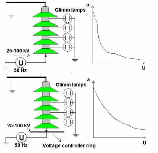
Here is the suspension Insulator's voltage distribution measure. We use Glimm lamps which light on a fix voltage, and it need very minimal current. The voltage distribution is not linear on the Insulator, because of it we use voltage controller rings. It compensate the capacity current with the steel pole, it is about equal with the wire capacity current. Bad thing: The first Insulator disc get the 70-80% of all voltage. If the first Insulator spark across, the others maybe will do it too, than the waved sea hop across the dam, and destroy it. Because of it are used spark horns, protect the Insulator chain. The Insulators is capacitors, the first problem is it in the open wire calculating. We look capacitors across the wire-pole, wire-wire and Insulator parts-pole, Insulator parts-wire and with earth too, it is about 4-5 page calculating...... uh.. I must learn it :-) Esa y part of it: - j * X = 1 / (2 * ¶ * f * C) f = 50 Hz C = capacity, which need calculate from the geometrical data (include some integrals ant other bad things). X = Reactance (capacitive resistance, ) -j = Complex algebra, it means minus 90 degrees vector (perpendicular). I = U / -j X Ohm law |